M.V. Keldysh Institute of Applied Mathematics RAS
e-mail:
Key words: texture compression, mip-mapping, wavelet transform.
The most significant requirements for texture compression are high decompression speed and local decompression ability. Besides, the decompression algorithm must be simple enough to be implemented in hardware.
Known texture compression approaches are based on vector quantization, codebooks, palletizing, look-up tables, etc. They have the following disadvantage: each pixel reconstruction requires references to two different areas of memory пїЅ the first to take index, the second to get the corresponding item from the palette or dictionary. The second memory fetch is dependent upon the first, and this amounts to a fatal flaw in this approach from the point of view of efficient HW implementation. Some alternatives include creating a special cache (usually a look-up table built into the 3D graphics pipeline) that can store the elements of the пїЅdictionaryпїЅ mentioned above. This also has a fatal flaw, namely that this dictionary becomes part of the texture state information, meaning that each texture may have itпїЅs own dictionary. Every time the application switches from one texture to the next, a new dictionary has to be installed in the hardware pipeline. As such texture switching is often very frequent, this technique would force us to flush the 3D graphics pipeline and install a potentially large block of data. The alternative is to require that all textures used in a scene must use the same dictionary, but this proves to be too restrictive.
One more texture compression approach is an algorithm proposed by the S3 Corp. called S3TC (S3 Texture compression)[3].
1.2.S3TCThe idea of the S3TC algorithm, is to split the initial image into 4x4 pixel blocks, and to perform compression for each block separately. Thus, all the information required for block decompression, is concentrated in one data structure.
The sixteen color values of each block are first approximated with only four and, of these, only two (base colors) are stored explicitly, the other two are derived from these base colors. Thus, each block is encoded by two color values in RGB565 format (2x16 bits), and, a matrix of 4x4 2-bit indices (32 bits). The compressed block size is 64 bits. This corresponds to 6-times compression for true-color images (initial block size 4x4x24 = 384 bits) and to 4-times compression for RGB565 images (initial block size 4x4x16 = 256 bits).
The fixed size of the blocks guarantees fast access to the particular block. The time of each pixel reconstruction is fixed. Switching between textures requires no delay.
Hierarchical methods such as wavelet decomposition[1] appeared to be rather effective for image compression. But they seem to be unsuitable for texture compression. Wavelet-based methods need tree-walk procedures which requires multiple accesses to memory. Though wavelet decomposition allows for local decompression, it still usually requires tree navigation operations.
On the other hand, some kind of hierarchical representation is desirable for textures. For texture mapping purposes the texture samples must be accessed at different resolution levels. The technique known as mip-mapping [2], [3], [4] is used to solve the problem. The idea is to store not only the initial texture image but also its 1:2, 1:4, 1:8, etc., (up to 1x1 pixel image) scaled copies.
We propose a method that combines the block-wise approach of S3TC with local hierarchical decomposition in each block. We try to unite the advantages of both approaches in our algorithm.
Advantages of Block-wise Approach:
Each block can be processed separately from other blocks. This allows for fast local decompression.
The size of all compressed blocks of a texture is fixed, so any given block can be found fast.
External information (which belongs not to single block but to the whole texture) is minimal, so switching between textures requires neither much memory nor much time.
Advantages of Hierarchical Approach:
Data belonging to a few resolution levels can be stored in each compressed block (in the case of 4x4 pixel blocks these are the 3 resolution levels 1x1, 2x2 and 4x4 pixels). Thus, compression and mip-mapping can be merged.
1.4.The Paper StructureThe rest of the paper is organized as follows: In Section 2 our method is described in detail, some results are introduced in Section 3. Section 4 is the conclusion.
2.The algorithm descriptionJust as with the S3TC algorith, the image is first split into 4x4 pixel blocks. All further processing is performed with each block separately.
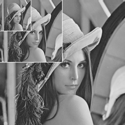
It is possible to build three resolution levels in each block: 1x1 pixels (low resolution), 2x2 pixels (medium resolution) and 4x4 pixels (high resolution). Thus three mip-maps can be coded in one file (see Fig. 1).
We chose the YCbCr color space for processing. The advantage of this color space is well known: even rather coarse approximation of chrominance (Cb and Cr) channels leads to good approximation of the whole image, this feature helps to increase compression ratio. Luminance (Y) and chrominance (Cb and Cr) channels are compressed separately.
On the other hand, such a choice requires additional operation while decompressing пїЅ conversion from YCbCr to RGB.
We experimented with a few different variants of compression of the channels. The experiments are not finished yet. So, here we describe the results of the experiments with one of these variants, we expect similar results from the others.
Fig. 1
3 resolution levels of image.
2.1.Luminance Analysis and Compression
First, two levels of 2D Haar wavelet decomposition are applied to intensity data. Thus, 16 luminance values are represented by:
1 mean luminance value,
3 wavelet coefficients of medium resolution level and,
12 wavelet coefficients of high-resolution level.
Then, the most significant wavelet coefficients are selected, namely, all 3 coefficients of the medium level and the 5 high-level coefficients with the largest absolute values.
The selected coefficients are encoded in the following way: The maximum absolute value is stored in an explicit form. Each coefficient is replaced by a 4-bit code, the first bit represents a sign, the others express the quotient of the maximum value required to represent the coefficient. Three bits allows coding of 8 levels from 1/8 to 8/8 of this maximum value.
As any wavelet coefficient of the high resolution level can be recognized as a significant one, a 12-bit mask is required to mark the places where coefficients were selected. Actually only 11 bits are enough for the mask as the 12th bit value is determined uniquely if the total amount of selected coefficients is known.
Thus the luminance of the block is encoded by 8 bits of mean luminance value, 7 bits of maximum coefficient absolute value (as it is at most half as large as the maximum possible low-resolution coefficient), (3+5)x4 bits for wavelet coefficient codes and 11 bits for the mask, 7+8+32+11=58 bits total.
Only two resolution levels (low level and medium level) are used for chrominance representation. The medium resolution level is enough for satisfactory high-resolution image representation. (This effect is used by JPEG compression algorithm).
The low resolution level is represented by 1 mean value per chrominance channel. The medium resolution level is approximated by 1 detailed coefficient multiplied by one of the 8 refining matrices and added to the mean value the low level. Fig. 2 demonstrates the set of refining matrices. Three bits for such a matrix index are required.
So, each channel has 8 bits for mean value, 8 bits for detailed coefficient and 3 bits for the matrix index required, 2x(8+8+3)=38 bits total.
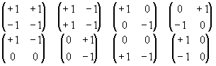
Fig. 2
The 8 refining matrices.
Thus, one block can be encoded by 58+38=96 bits or 12 bytes which corresponds to 4-times compression.
The structure of a compressed block can be organized as shown on Fig. 3.
The first 3 items represent the low resolution level of the block. They are followed by the values used for wavelet coefficient reconstruction. The next 3 items (WYm,1 пїЅ WYm,3) are the codes of the medium level wavelet coefficients. All this information is enough to reconstruct the medium level of the block.
Items Wb, Ib, Wr, and Ir, are detail coefficients and indices determining the medium level for Cb and Cr channels. WY,1 пїЅ WY5 are the codes for the high-level wavelet coefficients. The last item is a bit mask.
As mentioned above, the first three items of each block determine the singe pixel of the low frequency level.
To reconstruct the chrominance information, 1 step of reconstruction using a refining matrix is required for both color channels.
To reconstruct the luminance information of the medium resolution level, the corresponding wavelet coefficients must be decoded and one step of inverse wavelet transform is required.
To reconstruct a single pixel of the high-resolution level, the medium level should be reconstructed first. Then the corresponding wavelet coefficients must be decoded, and one additional step of inverse wavelet transform is required in the sub-block that the pixel belongs to. Four additional transforms are required to restore the whole level.
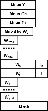
Fig. 3 Compressed block format
Thus, we used two kinds of operations: inverse Haar transform and reconstruction using a matrix. Let us estimate the complexity of both operations.
Here is a code fragment demonstrating the inverse Haar transform:
// c пїЅ coarse level value
// d1, d2, d3 пїЅ wavelet coefficients
// c1, c2, c3, c4 пїЅ fine level values
c1 = c + d1 + d2 + d3; c2 = c пїЅ d1 + d2 пїЅ d3;
c3 = c + d1 пїЅ d2 + d3; c4 = c пїЅ d1 пїЅ d2 + d2;
Reconstruction using matrices depends on the matrix type. Here is the case of the top-left matrix shown in Fig. 2. All other variants are similar.
// c пїЅ coarse level value
// d пїЅ detailed coefficient
// c1, c2, c3, c4 пїЅ fine level values
c1 = c + d; c2 = c1;
c3 = c пїЅ d; c4 = c3;
You can see that the operations are trivial, and can be easily implemented in hardware.
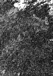
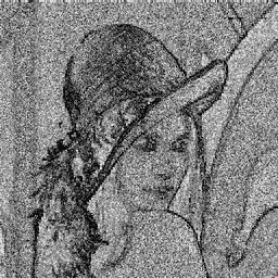
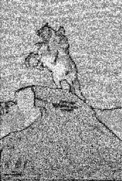
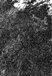
Our algorithm was tested on a sequence of images. The results were compared with those achieved using the S3TC algorithm. Some formal metrics (MSE, PSNR and LUV) were used to compare the reconstructed images with the original ones.
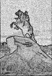
Fig. 4 displays three pictures and images demonstrating the difference between the originals and results of high resolution decompression using ours and the S3TC techniques. The difference was measured using the LUV metric. Areas of invisible differences are white, areas of nearly invisible difference are gray, and the areas of visible difference are black.
There seems to be no reason to demonstrate the compressed images themselves here, because when scaled and converted to gray-scale to fit into the paper text they look nearly the same as the originals.
Tab. 1 represents some numerical results of the comparison. The top figures are our algorithm results, the bottom figures are S3TC results. The last 3 columns are the results of the LUV metric. Diff0, Diff1 and Diff2 are percentages of white, gray and black areas in the corresponding difference images.
4.Conclusion. Further research
We have developed a method performing texture compression with local hierarchical decomposition. It yields 4X compression of true-color images. This is the compression ratio for a file containing 3 mip-maps (original size, 1/4 and 1/16 resolution). (The compression ratio of S3TC is 6 times, but only for a single map. The compression ratio for a file containing 3 mip-maps is (1 + 1/4 + 1/16)/6 = 0.21875 or 4.57 times for S3TC).
As with the S3TC algorithm, all the data required for block decompression is concentrated into a single structure, so the method allows for local decompression and doesnпїЅt require any texture switching operations.
Some parameters, such as the amount of bits for wavelet coefficient representation and the amount of significant coefficients can be varied. This can increase the compression ratio, but unfortunately affects image quality.
Our experiments are not finished yet. We are sure that we can successfully increase either the compression ratio or the quality. One possible refinement, is to classify blocks somehow, and to use different methods to compress each class of blocks. Some experiments of this kind were already performed.
Although the fixed compression ratio and fixed block size relieve the decompression process of many complexities, this cannot guarantee both good compression ratio and high quality. It is obvious, that areas containing less high-frequency information can be compressed better and vice versa. Is it possible to code efficiently, areas with different frequency characteristics without increasing decompression time significantly? This is a task for further research.
This work was made as a part of research program performed in accordance with the Research Agreement between Moscow State University and Intel Technologies, Inc.
Thanks to Jim Hurley (Intel Corporation) for help with composing the paper. Thanks to Sergey Titov (CMC dept., MSU), for image distortion metrics program.
1. E.J. Stollnitz, T.D.Derose, D.H.Salesin. Wavelets for Computer Graphics. Theory and Applications. Morgan Kaufmann Publishers, Inc., San Francisco, California, 1996.
2.A. Watt, M. Watt. Advanced Animation and Rendering Techniques. Theory and Practice. ACM Press, New York, 1992.
3.S3TC DirectX 6.0 Standard Texture compression. White paper, S3 Corp.|
MSE |
PSNR |
Diff0 |
Diff1 |
Diff2 |
|
|
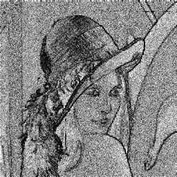
Lena |
1.35 |
38.7 |
21 |
60 |
19 |
|
Peter I |
1.1 |
39.5 |
43 |
50 |
7 |
|
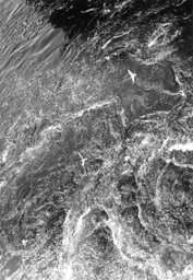
Water |
8.7 |
30.6 |
9 |
43 |
48 |
|
Lena (512x512 pels) |
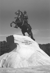
Peter I (345x512 pels) |
Water (353x512 pels) |
|
|
Initial image |
|
|
|
|
HTC |
|
|
|
|
S3TC |
|
|
|
Fig. 4. Some results.